REVISION 1.00
Project Lockdown
4/15/2020 | David Jones
After deciding to create a 100% 3D printable nano frame. I spoke with Dale and Jadon, two pilot's on the team who have a bunch of experience with these tiny frames, just to get the ball rolling and kick us off in the right direction.
Jadon was excited from the get-go and wanted to print it ASAP to get an idea of how rigid and stiff it would be. Dale was a little more hesitant since he's had loads of experience with this style of frame and has tried previously to fly printed frames with mixed results.
These were Dale's concerns:
1. Motors run way hotter than usual and there is a risk of the motor bolts melting the print material (PLA especially).
2. Frames are generally much heavier than conventional carbon frames with a lot more flex.
3. Materials like PLA and PETG tend to not break but rather explode in crashes.
These were all very real concerns (although melting the frame due to hot motor bolts, I didn't anticipate). So we are working with a material, regardless of the specific plastic flavour, which has far less stiffness and strength when compared to carbon fibre. The one massive draw-card we do have in our favour is the the beautiful moulded shapes and surfaces we can create which are just not possible with regular carbon fibre plate and bolt frames.
We will have to create surfaces with as few sharp corners as possible, this will both reduce the weight if we think smart and reduce the risk of the chassis "exploding" as Dale put it.
With this in mind I created a pretty crude arm and motor mount assembly just to test out how stiff it would be in PLA.
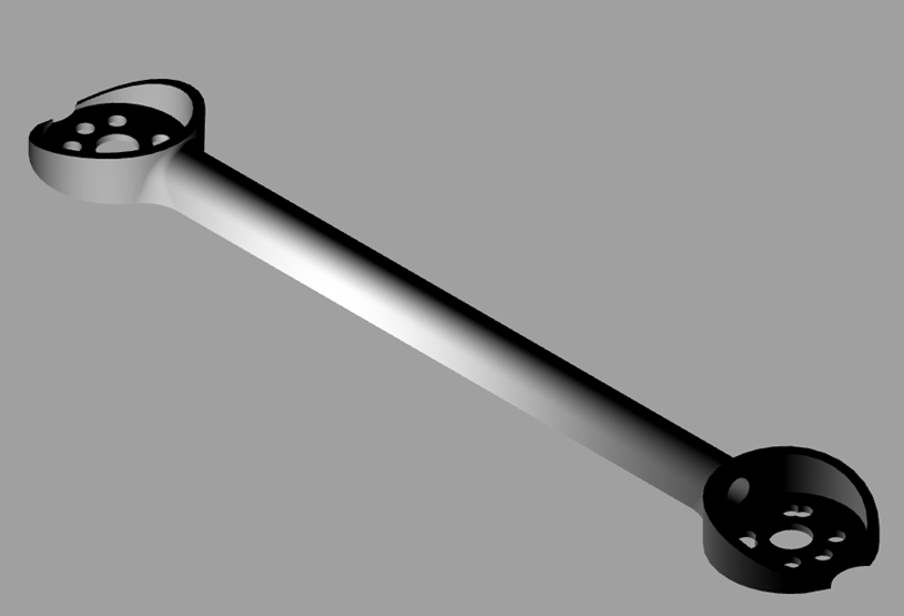 This was the first arm test I did, printed in PLA in 0.4mm width and 0.15mm layer heights. I was honestly surprised with how much torsional stiffness the arm had, but only being 3 layers thick around the the hole in the centre of the arm, it just didn't have the bending stiffness I thought it would need.
So on to the next arm revision. I really liked the idea of routing motor wires down the inside of the arm. This would protect from prop strikes but would also give us a more semi-monocoque structure which we would like to approach.This will maximise structural integrity while keeping the weight down. I thought giving it a proper airfoil shape wouldn't harm aerodynamic efficiency and it would also give us a bit more height which would help with the bending stiffness the previous arm was lacking.
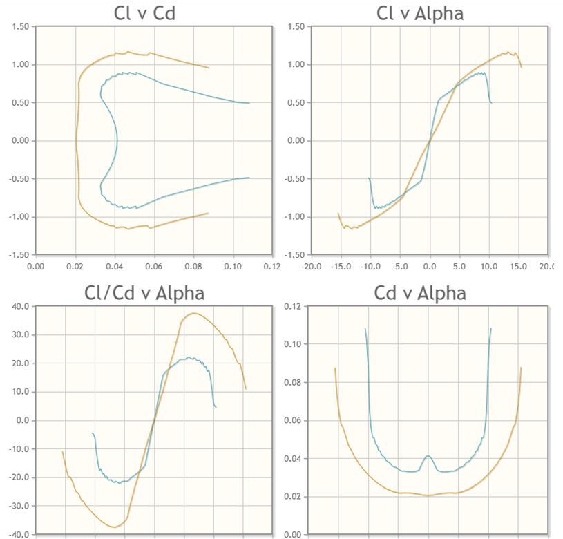
I went through a couple of 4 series NACA airfoils which have good low Reynold's number characteristics and decided on a NACA 0018 airfoil. I set the Ncrit value to 9 and ran it through a range of 50000 - 100000 for the Reynolds number as this is as low as I could run it and still generate some graphs.
I used airfoiltools.com to compare and generate the graphs.
I selected the 0018 as it generated predictable curves and it fitted around the motor wire routing hole in the centre of the arm the best.
I was pretty happy with how the second arm looked, increased the wall thickness to 4 layers and bumped up the base thickness a bit just to give it a little more material around the base of the motor. I was still concerned at what Dale had mentioned about the motors getting crazy hot.
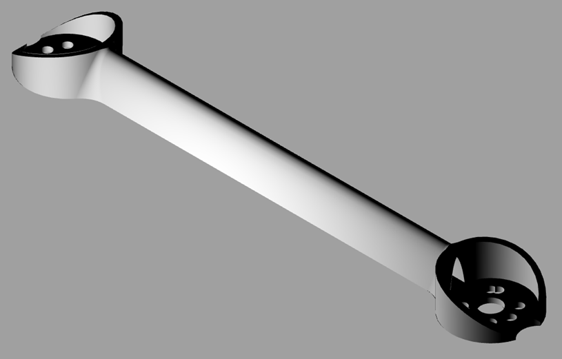 The torsional stiffness was still really impressive, probably even higher than a traditional 2mm thick carbon arm. The bending stiffness had also gone up quite substantially, so I thought this would be a good starting point. The blended fillet between the arm and the motor base made a big difference and the shroud "cup" around the motor made the motor mount base pretty rigid too.
On to the frame itself. I played around with a couple of different centre section ideas, but they all seemed clunky, adding too much weight and material where it wasn't going to be used effectively. There is no point in having excess material not working to its maximum if the arms towards the outside of the chassis are getting over-stressed. I wanted to keep the flexibility of mounting a 16X16mm stack or an AIO, which you can do, but I gave priority to the AIO whoop style board for now.
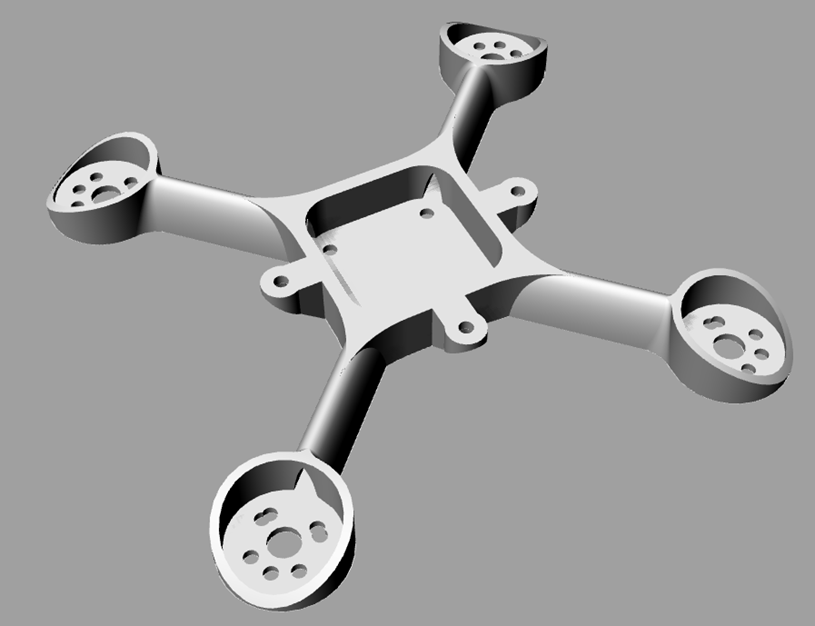
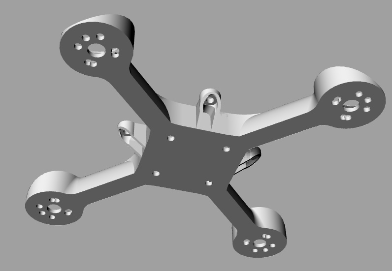
REV1.00 topish view
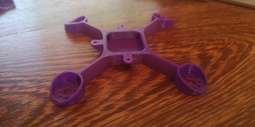
 REV1.00 bottomish view
So this is the first revision, it's a 95mm frame designed for 2" props. I printed it out of PLA and felt the stiffness was definitely on par with similar 2mm carbon frames although this hasn't yet been flown so we still don't know how it will handle a crash yet. It weighs 8.7 grams as seen in the images above.
It's been designed around a 0.4mm nozzle and it printed really well in 0.15mm layers. Print it flat on its base, it will print without any support in under an hour.
I thought the centre lunchbox cavity would be pretty cool for hiding a nano vtx and RX (RXSR or similar) although removing all the cross beams in the centre does create a bit more flex in the middle, I don't think this will be an issue.
The 4 holes in the base of the chassis are for 16X16mm stacks and the outer 3 tabs will mount an AIO just above the lunchbox.
You'll find the (frame name to be decided) REV1.00 STL file below:
Please leave your suggestions and comments below, so everyone can follow along and see the progress.
Oh, and please leave some name suggestions for this frame :)